Digital
The digital module in the Qili SDK facilitates the construction and simulation of digital quantum systems. It is composed of the following primary components:
gates: A collection of quantum gates and tools for gate construction.Circuit: A class to create and manage digital quantum circuits.ansatz: Predefined circuits that can serve as Ansätze.
Gates
This submodule provides the necessary components to define and manipulate quantum gates for use in digital quantum circuits.
Simple Gates
Use these constructors to apply standard single- and two-qubit operations:
X(qubit: int)Pauli X (bit-flip) on the specified qubit.Y(qubit: int)Pauli Y (bit-and-phase-flip).Z(qubit: int)Pauli Z (phase-flip).H(qubit: int)Hadamard: creates superposition.I(qubit: int)Identity gate: leaves the qubit unchanged.S(qubit: int)Phase gate (π/2 rotation about Z).T(qubit: int)T gate (π/4 rotation about Z).RX(qubit: int, theta: float | Parameter | Term)Rotation by angle theta around X.RY(qubit: int, theta: float | Parameter | Term)Rotation by angle theta around Y.RZ(qubit: int, phi: float | Parameter | Term)Rotation by angle phi around Z.U1(qubit: int, *, phi: float | Parameter | Term)Phase shift equivalent to RZ plus global phase.U2(qubit: int, *, phi: float | Parameter | Term, gamma: float | Parameter | Term)π/2 Y-rotation sandwiched by Z-rotations.U3(qubit: int, *, theta: float | Parameter | Term, phi: float | Parameter | Term, gamma: float | Parameter | Term)General single-qubit unitary: RZ-RY-RZ decomposition.SWAP(a: int, b: int)Exchanges the states of qubitsaandb.CNOT(control: int, target: int)Controlled-X: flips target if control is |1⟩.CZ(control: int, target: int)Controlled-Z: applies Z on target if control is |1⟩.M(*qubits: int)Measures the listed qubits in the computational basis.
Controlled Gates
Any basic gate can be turned into a controlled gate using the Controlled class:
from qilisdk.digital.gates import Controlled, Y

controlled_y = Controlled(0, basic_gate=Y(1))
multiple_controlled_y = Controlled(0, 1, basic_gate=Y(2))
Or alternatively, you can use the .controlled() method on any gate instance:
from qilisdk.digital.gates import Y

controlled_y = Y(1).controlled(0)
multiple_controlled_y = Y(2).controlled(0, 1)
Adjoint Gates
You can create the Hermitian conjugate (dagger) of a gate using the Adjoint class:
from qilisdk.digital.gates import Adjoint, Y

adjoint_y = Adjoint(basic_gate=Y(1))
Exponential Gates
To apply a gate as an exponential operator, use the Exponential class:
from qilisdk.digital.gates import Exponential, Y

exp_y = Exponential(basic_gate=Y(1))
Circuits
Quantum circuits can be built using the Circuit class. You can sequentially add gates to define the circuit:
Initialization
from qilisdk.digital import Circuit

# Create a 3-qubit circuit
circuit = Circuit(nqubits=3)
Adding Gates
from qilisdk.digital import H, CNOT
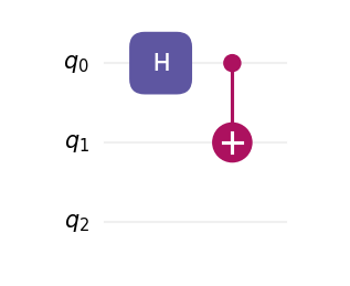
circuit.add(H(0)) # Hadamard on qubit 0
circuit.add(CNOT(0, 1)) # CNOT: control 0 → target 2
circuit.draw()
You can also add or insert multiple gates at once:
from qilisdk.digital import X, RX
import numpy as np

circuit.add([X(0), RX(1, theta=np.pi / 2)])
circuit.insert([H(2), CNOT(2, 1)], index=1)
circuit.insert(X(0), 0)
Circuits can be appended or prepended, and the + operator mirrors those behaviors:
left = Circuit(2)
left.add(H(0))

right = Circuit(2)
right.add(CNOT(0, 1))

left.append(right)
# Equivalent: left = left + right

extra = X(1)
# Equivalent to left.insert(extra, index=0)
left = extra + left
Generating Random Circuits
You can also initialize a random circuit with a specified number of gates using the random() method:
from qilisdk.digital import Circuit, X, H, CNOT
c = Circuit.random(
    nqubits=3,
    single_qubit_gates=[X, H],
    two_qubit_gates=[CNOT],
    ngates=10,
)
circuit.draw()
Parameterized Circuits
Circuits can include parameterized gates. Adding them is similar to regular gates:
from qilisdk.digital import RX
import numpy as np

circuit.add(RX(0, theta=np.pi))
You can retrieve the current parameter using:
print("Initial Parameters:", circuit.get_parameters())
Output:
Initial Parameters: {'RX(0)_theta_0': 3.141592653589793}
You can also retrieve a list containing only the current parameter values:
print("Initial parameter values:", circuit.get_parameter_values())
Output:
Initial parameter values: [3.141592653589793]
To update parameters by their keys:
circuit.set_parameters({"RX(0)_theta_0": 2 * np.pi})
To update all parameters with new values:
circuit.set_parameter_values([2 * np.pi])
Warning
The order of parameters in the list passed to set_parameter_values must match the order in which the gates were added to the circuit.
Visualization
Use draw() to render a circuit with Matplotlib.
By default, the renderer applies the library’s built-in styling (including the bundled default font if available).
You can bypass all defaults by passing a custom CircuitStyle, which
confines styling to the specific call without modifying global Matplotlib settings.
from qilisdk.digital import Circuit, H, CNOT

circuit = Circuit(num_qubits=3)
circuit.add(H(0))
circuit.add(CNOT(0, 2))

# Render in a window
circuit.draw()
Output
Saving to a file
# Save as SVG (use .png, .pdf, etc. as needed)
circuit.draw(filepath="my_circuit.svg")
Custom styling with CircuitStyle
Create a style object to control theme, fonts, spacing, DPI, labels, and more. Passing this object to draw() overrides the library defaults for this call.
You can also change if the order of the draw follows the order they are added in or if it compacts the layers as much as possible by changing the parameter layout to “normal” (default) or “compact” respectively.
from qilisdk.digital import Circuit, H, CNOT
from qilisdk.utils.visualization import CircuitStyle, light, dark

circuit = Circuit(3)
circuit.add(H(0))
circuit.add(CNOT(0, 2))

# Example 1: dark theme, larger text, higher DPI
style_dark = CircuitStyle(
    theme=dark,
    dpi=200,
    fontsize=12,
    title="Teleportation (fragment)",
)
circuit.draw(style=style_dark)

# Example 2: use a system font family and bypass the bundled font
style_font = CircuitStyle(
    theme=light,
    fontfname=None,                         # do not force a specific TTF file
    fontfamily=["DejaVu Sans", "Arial"],    # fallback list
    fontsize=11,
)
circuit.draw(style=style_font, filepath="circuit_custom_font.png")

# Example 3: adjust layout spacing
compact = CircuitStyle(
    theme=dark,
    wire_sep=0.45,      # vertical distance between wires (inches)
    layer_sep=0.45,     # horizontal distance between layers (inches)
    gate_margin=0.10,   # side margin inside each layer cell (inches)
    label_pad=0.08,     # left padding for wire labels (inches)
    layout="compact",   # compresses the circuit whenever possible
    title="Compact layout",
)
circuit.draw(style=compact)
Note
CircuitStyle fields map directly to the renderer’s layout and font configuration. In particular, you can switch fonts in two ways:
(1) provide a specific font file via fontfname="/path/to/MyFont.ttf"; or
(2) set fontfname=None and choose a family list with fontfamily=[...] to use system-resolved fonts. Both approaches only affect the current draw call.
Ansatz
The ansatz submodule provides ready-to-use circuit templates (Ansätze) and a lightweight framework for writing your own. To author a custom template:
Call
super().__init__(nqubits=...)inside__init__to set the circuit width.Add gates in any order with
self.add(gate)—loops are fine, and you can keep references to anyParameterobjects you want to expose later.
Example
from qilisdk.core.variables import Parameter
from qilisdk.digital import H, RX, CZ
from qilisdk.digital.ansatz import Ansatz

class NewAnsatz(Ansatz):
    def __init__(self, nqubits: int, beta: float):
        super().__init__(nqubits=nqubits)
        self.beta = Parameter("beta", value=beta)

        # Layer 1: put each qubit in superposition
        for q in range(self.nqubits):
            self.add(H(q))

        # Layer 2: simple linear entangler
        for q in range(self.nqubits - 1):
            self.add(CZ(q, q + 1))

        # Layer 3: parameterized mixer
        for q in range(self.nqubits):
            self.add(RX(q, theta=self.beta))
Once defined, the subclass behaves exactly like any other circuit—you can draw it, bind parameters, or hand it off to backends.
For a prebuilt option, consider:
HardwareEfficientAnsatz
HardwareEfficientAnsatz is a hardware-efficient ansatz tailored to quantum device topologies. Configuration options:
layers: Number of repeating layers of gates.
connectivity:
circular: Qubits form a ring.linear: Qubits are connected linearly.full: All-to-all connectivity.Or a list of tuples explicitly specifying the connectivity.
one_qubit_gate: Choose the parameterized single-qubit gate (e.g.,
U1,U2,U3).two_qubit_gate: Choose the two-qubit interaction type (e.g.,
CNOT,CZ).structure:
grouped: Applies all single-qubit gates first, followed by all two-qubit gates.interposed: Interleaves single and two-qubit gates.
Example
from qilisdk.digital.ansatz import HardwareEfficientAnsatz
from qilisdk.digital import U3, CNOT


ansatz = HardwareEfficientAnsatz(
    nqubits=4,
    layers=3,
    connectivity="Circular",
    one_qubit_gate=U3,
    two_qubit_gate=CNOT,
    structure="Interposed"
)
ansatz.draw()
This ansatz can then be used as a circuit. For example, we can execute this ansatz using QuTiP backend (need to be installed separately):
from qilisdk.backends import QutipBackend
from qilisdk.functionals import Sampling

backend = QutipBackend()

backend.execute(Sampling(ansatz))
QAOA
QAOA is an ansatz applying the alternating time evolution of a
problem Hamiltonian and a mixer Hamiltonian [1].
By initializing the circuit as the ground state of the mixer Hamiltonian (often simply the uniform superposition) and then
applying the alternating evolution scaled by parameters \(\gamma_i\) and \(\alpha_i\), the idea is that at a certain set of
parameters the ansatz should approximate the evolution from the ground state of the mixer Hamiltonian to the ground state of the problem Hamiltonian,
as per the quantum adiabatic theorem. By treating this parameterized circuit as an ansatz for a variational quantum algorithm, we can optimize
to try to minimize the expectation value of the problem Hamiltonian and thus solve the encoded optimization problem.
Configuration options:
problem_hamiltonian: The problem Hamiltonian encoding the cost function.
layers: Number of repeating layers of gates. Each layer applies two evolutions: one for the problem Hamiltonian and one for the mixer Hamiltonian.
mixer_hamiltonian: The mixer Hamiltonian. Defaults to X mixer.
trotter_steps: Number of Trotter steps to use for Hamiltonian approximation. Only used if the Hamiltonians contains non-commuting terms.
problem_params: Initial parameter values for the problem Hamiltonian evolution angles. Defaults to 0.0 for all layers.
mixer_params: Initial parameter values for the mixer Hamiltonian evolution angles. Defaults to 0.0 for all layers.
Example
from qilisdk.digital import QAOA, Z

problem_hamiltonian = Z(0) * Z(1) + Z(2)
ansatz = QAOA(
    problem_hamiltonian=problem_hamiltonian,
    layers=2,
    mixer_hamiltonian=None,
    trotter_steps=1
    problem_params=[0.5, 1.0],
    mixer_params=[0.25, 0.75]
)
ansatz.draw()
As with the HardwareEfficientAnsatz, this ansatz can then be used as per any QiliSDK circuit.
Or, to instead perform variational optimization over the parameters to minimize the
expectation value of the problem Hamiltonian, one can set up a VariationalProgram (see Functionals for more details):
from qilisdk.functionals.variational_program import VariationalProgram
from qilisdk.optimizers.scipy_optimizer import SciPyOptimizer
from qilisdk.cost_functions.observable_cost_function import ObservableCostFunction

vqa = VariationalProgram(functional=Sampling(ansatz),
                         optimizer=SciPyOptimizer(method="powell", tol=1e-7),
                         cost_function=ObservableCostFunction(problem_hamiltonian))

print(f"Running QAOA with {len(ansatz.get_parameters())} parameters...")
backend = QutipBackend()
result = backend.execute(vqa)
print("VQA Result:", result)
TrotterizedTimeEvolution
TrotterizedTimeEvolution builds a digital circuit that follows a
time-ordered schedule of Hamiltonians. Each schedule slice is evolved using a fixed number of
Trotter steps, and you may optionally prepend a state-initialization circuit or list of gates.
Configuration options:
schedule: A
Scheduleof Hamiltonians to trotterize.trotter_steps: Number of Trotter steps per schedule slice. Defaults to 1.
Example
from qilisdk.analog.hamiltonian import Z as pauli_z
from qilisdk.analog.schedule import Schedule
from qilisdk.digital.ansatz import TrotterizedTimeEvolution

hamiltonian = pauli_z(0)
schedule = Schedule(
    hamiltonians={"h": hamiltonian},
    dt=0.1,
    total_time=1
)
ansatz = TrotterizedTimeEvolution(
    schedule=schedule,
    trotter_steps=1,
)
ansatz.draw()
Parameter Utilities
Circuits collect the symbolic parameters contributed by each gate. Beyond the quick examples above, you can query names, current values, and bounds, or update them selectively:
import numpy as np

from qilisdk.core.variables import Parameter
from qilisdk.digital import Circuit, RX, RZ

circuit = Circuit(nqubits=2)
theta = Parameter("theta", value=np.pi / 4, bounds=(0.0, np.pi))

circuit.add(RX(0, theta=theta))
circuit.add(RZ(1, phi=np.pi / 2))

print(circuit.get_parameter_names())   # ['RX(0)_theta_0', 'RZ(1)_phi_1']
print(circuit.get_parameters())        # {'RX(0)_theta_0': 0.785..., 'RZ(1)_phi_1': 1.570...}
print(circuit.get_parameter_bounds())  # {'RX(0)_theta_0': (0.0, 3.1415...), 'RZ(1)_phi_1': (None, None)}

circuit.set_parameter_bounds({"RX(0)_theta_0": (0.1, np.pi / 2)})
circuit.set_parameters({"RX(0)_theta_0": np.pi / 3})
circuit.set_parameter_values([np.pi / 3, np.pi / 2])
These helpers make it straightforward to plug the circuit into classical optimization loops while keeping parameter metadata synchronized.
Note
Parameterized gates and circuits expose parameter information through
get_parameter_names, get_parameters, get_parameter_values, and
the matching set_* methods.
Gate Modifiers and Measurement
Every base gate inherits convenience methods to produce derived operations
without manually instantiating Controlled,
Adjoint, or
Exponential. The measurement gate
M lets you add classical readout at the end of
the circuit.
import numpy as np

from qilisdk.digital import Circuit, H, X, RX, M

circuit = Circuit(2)
circuit.add(H(0))

# Promote a basic gate to a controlled version on the fly
circuit.add(X(1).controlled(0))

# Generate adjoint / exponential variants, preserving parameters
circuit.add(RX(1, theta=np.pi / 4).adjoint())
circuit.add(RX(0, theta=np.pi / 3).exponential())

# Record measurement results for both qubits
circuit.add(M(0, 1))
Controlled gates validate that control and target qubits are disjoint, and all wrapper gates forward parameter accessors to the underlying operation.
Note
The measurement gate cannot be controlled, conjugated, or exponentiated.
If a circuit ends without explicit measurements, the backend assumes all qubits are measured.
Measuring only a subset of qubits returns samples for that subset.