Circuits
Quantum circuits can be built using the Circuit class. You can sequentially add gates to define the circuit:
Initialization
from qilisdk.digital import Circuit

# Create a 3-qubit circuit
circuit = Circuit(nqubits=3)
Adding Gates
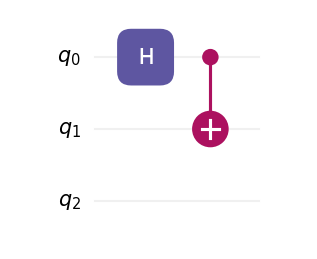
from qilisdk.digital import H, CNOT

circuit.add(H(0))  # Hadamard on qubit 0
circuit.add(CNOT(0, 1))  # CNOT: control 0 → target 2
circuit.draw()
You can also add or insert multiple gates at once:
from qilisdk.digital import X, RX
import numpy as np

circuit.add([X(0), RX(1, theta=np.pi / 2)])
circuit.insert([H(2), CNOT(2, 1)], index=1)
circuit.insert(X(0), 0)
Circuits can be appended or prepended, and the + operator mirrors those behaviors:
left = Circuit(2)
left.add(H(0))

right = Circuit(2)
right.add(CNOT(0, 1))

left.append(right)
# Equivalent: left = left + right

extra = X(1)
# Equivalent to left.insert(extra, index=0)
left = extra + left
Generating Random Circuits
You can also initialize a random circuit with a specified number of gates using the random() method:
from qilisdk.digital import Circuit, X, H, CNOT
c = Circuit.random(
    nqubits=3,
    single_qubit_gates=[X, H],
    two_qubit_gates=[CNOT],
    ngates=10,
)
circuit.draw()
Parameterized Circuits
Circuits can include parameterized gates. Adding them is similar to regular gates:
from qilisdk.digital import Circuit, RX
import numpy as np

circuit = Circuit(1)
circuit.add(RX(0, theta=np.pi))
You can retrieve the current parameter using:
print("Initial Parameters:", circuit.get_parameters())
Output:
Initial Parameters: {'RX(0)_theta_0': 3.141592653589793}
You can also retrieve a list containing only the current parameter values:
print("Initial parameter values:", circuit.get_parameter_values())
Output:
Initial parameter values: [3.141592653589793]
To update parameters by their keys:
circuit.set_parameters({"RX(0)_theta_0": 2 * np.pi})
To update all parameters with new values:
circuit.set_parameter_values([2 * np.pi])
Warning
The order of parameters in the list passed to set_parameter_values must match the order in which the gates were added to the circuit.
Visualization
Use draw() to render a circuit with Matplotlib.
By default, the renderer applies the library’s built-in styling (including the bundled default font if available).
You can bypass all defaults by passing a custom CircuitStyle, which
confines styling to the specific call without modifying global Matplotlib settings.
from qilisdk.digital import Circuit, H, CNOT

circuit = Circuit(3)
circuit.add(H(0))
circuit.add(CNOT(0, 2))

# Render in a window
circuit.draw()
Output
The plot can also be saved to a file by providing a filepath to the draw method:
# Save as SVG (use .png, .pdf, etc. as needed)
circuit.draw(filepath="my_circuit.svg")
Custom styling with CircuitStyle
Create a style object to control theme, fonts, spacing, DPI, labels, and more. Passing this object to draw() overrides the library defaults for this call.
You can also change if the order of the draw follows the order they are added in or if it compacts the layers as much as possible by changing the parameter layout to “normal” (default) or “compact” respectively.
from qilisdk.digital import Circuit, H, CNOT
from qilisdk.utils.visualization import CircuitStyle, light, dark

circuit = Circuit(3)
circuit.add(H(0))
circuit.add(CNOT(0, 2))

# Example 1: dark theme, larger text, higher DPI
style_dark = CircuitStyle(
    theme=dark,
    dpi=200,
    fontsize=12,
    title="Teleportation (fragment)",
)
circuit.draw(style=style_dark)

# Example 2: use a system font family and bypass the bundled font
style_font = CircuitStyle(
    theme=light,
    fontfname=None,                         # do not force a specific TTF file
    fontfamily=["DejaVu Sans", "Arial"],    # fallback list
    fontsize=11,
)
circuit.draw(style=style_font, filepath="circuit_custom_font.png")

# Example 3: adjust layout spacing
compact = CircuitStyle(
    theme=dark,
    wire_sep=0.45,      # vertical distance between wires (inches)
    layer_sep=0.45,     # horizontal distance between layers (inches)
    gate_margin=0.10,   # side margin inside each layer cell (inches)
    label_pad=0.08,     # left padding for wire labels (inches)
    layout="compact",   # compresses the circuit whenever possible
    title="Compact layout",
)
circuit.draw(style=compact)
Note
CircuitStyle fields map directly to the renderer’s layout and font configuration. In particular, you can switch fonts in two ways:
(1) provide a specific font file via fontfname="/path/to/MyFont.ttf"; or
(2) set fontfname=None and choose a family list with fontfamily=[...] to use system-resolved fonts. Both approaches only affect the current draw call.
Parameter Utilities
Circuits collect the symbolic parameters contributed by each gate. Beyond the quick examples above, you can query names, current values, and bounds, or update them selectively:
import numpy as np

from qilisdk.core.variables import Parameter
from qilisdk.digital import Circuit, RX, RZ

circuit = Circuit(nqubits=2)
theta = Parameter("theta", value=np.pi / 4, bounds=(0.0, np.pi))

circuit.add(RX(0, theta=theta))
circuit.add(RZ(1, phi=np.pi / 2))

print(circuit.get_parameter_names())   # ['RX(0)_theta_0', 'RZ(1)_phi_1']
print(circuit.get_parameters())        # {'RX(0)_theta_0': 0.785..., 'RZ(1)_phi_1': 1.570...}
print(circuit.get_parameter_bounds())  # {'RX(0)_theta_0': (0.0, 3.1415...), 'RZ(1)_phi_1': (None, None)}

circuit.set_parameter_bounds({"RX(0)_theta_0": (0.1, np.pi / 2)})
circuit.set_parameters({"RX(0)_theta_0": np.pi / 3})
circuit.set_parameter_values([np.pi / 3, np.pi / 2])
These helpers make it straightforward to plug the circuit into classical optimization loops while keeping parameter metadata synchronized.
Note
Parameterized gates and circuits expose parameter information through
get_parameter_names, get_parameters, get_parameter_values, and
the matching set_* methods.